David Preiss
project description

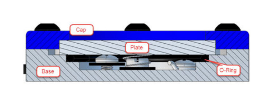
If you're curious what air bearings are - they're an alternative to plain or rolling element bearings that use a fluid (air) interface to allow for frictionless constraint without part to part contact. They're generally used in high precision applications (semiconductor fab, linear motion in CMMs, >60k rpm spindles). One incredibly cool application is in Dan Gelbart's video on the single micron tolerance lathe he built out of granite parallels and air bearings.
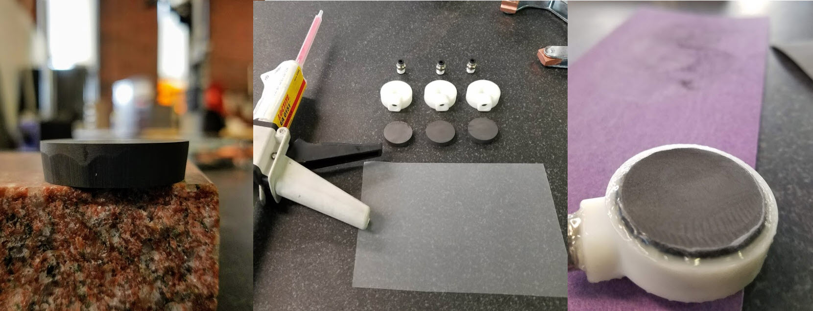
There's an abundant supply of graphite available on the internet that's used for machining sinker EDM tools. You can buy it new in small quantities but there are also plenty of cutoffs used by machine shops for cutting injection molding tools. I ordered some cheap rectangular pieces of graphite through ebay, printed a plenum, and epoxied an NPT push connect fitting into the plenum, and that to the graphite (the actual first one was just a square plenum with no positive mechanical connection and urethane CA which at ~40 psi shot the graphite across the room. After that I started thinking a little more about the mechanical connection and ground a chamfer into the graphite to provide some dovetailing + two rings of grooves in the plenum which allowed for actual positive mechanical engagement of the graphite. In contrast to the thumbnail this is what my first attempt looked like - some small amount of flow but most of it was coming through a visible defect in the graphite.
So despite some small bubbling, this attempt was unsuccessful. Around this time I started to worry about the thickness of my sample (which was already at a very narrow 8 mm). My other concern which happened to be the more warranted one was in questioning the open porosity of my stock (ie. how connected were all of the pores of the sample as opposed to just being single isolated cells. After some more detailed googling it became evident that there is a lot of nuance to various graphite grades. I stumbled upon a company called POCO Graphite that markets particularly isotropic grain/pore size/mechanical properties/particular manufacturing process controls. Their website has detailed descriptions of air bearing microstructure/mechanical properties, down to pore size, and percent open porosity. It was also clear that many of their EDM grades shared similar pore size and density (open porosity percentage is only listed for their "industrial" or air bearing grades. You can see more air Bearing graphite information here and here
It seems as though workable parameters for air bearing graphite envelopes:
- 1 to 5 microns (with most being 5).
- 0.3 to 0.8 micron pore size.
- 20%-26% pororse by volume.
- 75% - 90% open porosity by total.
- Apparent density between 1.66 - 1.78 g/cm^3.
- Particle size under 5 microns (they don't really make it clear what this means but I'm assuming it roughly correlates with pore size.
- Density around 1.72 g/cm^3 (this one was hard to find but I got it from looking at tensile strength across two graphs that showed density)
- A bunch of flexural properties and other data accessible tracks within the range of graphites graded for air bearings
I made another prototype (this one with the more sophisticated retention features) and to my surprise it actually worked. Upon submerging it's pretty night and day in terms of air flow. The puck took a significant amount of force to ground by hand (I didn't get any numbers at this point). It's likely that what separates POCO's various grades is process control and some degree of just binning by porosity/density/other, so I would strongly encourage folks to try with the cheap stuff.
Graphite machines decently well (despite probably doing irreparable damage to end mills). It's important to have good vacuum for respiratory reasons, but also to make sure you don't wind up with a bunch of abrasive carbon dust in your machine's ways. My workflow was to vertical bandsaw, and then face both sides of the graphite puck. I don't have any data on this but it felt important to keep thickness uniform to guarantee equal pneumatic resistance and therefore flow across the graphite. My other assumption was that the area within the plenum achieved some steady state pressure and that flow would be equal without needing significant height to the plenum to open up the flow.
I lapped the graphite to 600 grit on a surface plate after machining. I then epoxied the plenum on over a PP film stuck to a surface plate, and allowed the resin to flow down the sides of the graphite puck, completely sealing off the edges of the puck (and creating that mechanical interference on the dovetail from earlier). I used LOCTITE® EA 0151, but don't think the epoxy matters much. After curing, I re lap the face of the graphite to bring any excess epoxy that's worked its way under the puck into plane. Porous air bearings can tolerate a good amount of exposed porous surface, so no need to be too meticulous. I was concerned with the idea of lapping both sides of the puck considering that one side would be subject to positive pressure and all of the smaller particles ground into the porous structure would effectively clog the bearing (not a problem on the bearing side where those particles would just be ejected. It takes less than a minute to lap in graphite to sub 20 micron flatness. It also helps that all of the pucks I've made are under 40 mm in diameter. It's important to frequently unclog the sand paper, especially at higher grits, otherwise you'll just ride around on a bed of graphite dust which is actually extremely lubricious. Tom Lipton has an amazing series of videos on lapping that were helpful to watch:
Planar Air Bearings
So a single planar air bearing like the one above is sort of useless on its own. Three of them on a flat surface make a planar bearing with gravity to provide the preload. By printing plenums with kinematic female imprints of concave tetrahedrons, I was able to get closer to something practical. The concave tetrahedrons function as ball joints, whereas the ball in this case is an inverted BHSCS. I was inspired to go this route by markforged's use of a kinematic coupling in their build plate mounting feature on their Mark II printer. Thumb nuts on top allow the stage to be adjusted into parallelism with the surface plate if desired. The final result is a frictionless bearing that tracks extremely well with the flatness of whatever surface it floats on. The dial indicator is hard to see in the video, but is tracking within sub single micron readings on a 2 um/division test indicator. I was pressing on it to try and get an idea of how rigid the stage was and you can also see it shifting by about 10 microns of deflection at the indicator (exacerbated by a large moment arm). This is why most systems using air bearings have an opposing bearing, or some magnetic or vacuum preload. I was able to float this setup on a piece of pretty carelessly faced aluminum as well, so at least at the bearing diameter I've chosen it doesn't seem to be too intolerant to global flatness issues.. The ball joints are particularly helpful if that's what you're after. Another option would be to adhesive 3 bearings to a stage while resting on a surface plate, which can probably net more stiffness at the cost of modularity and tolerance to surface flatness. The next logical step here would be to make a linear stage out of one of these. Until then I can't think of many useful applications. It could be neat to try sticking with 3 bearings by using a granite v-groove, but the way I'll probably do this is with another set of 3 bearings and a granite parallel (only 2 are needed for line contact but we still need something to preload with).Rotary Air Bearings
The planar bearing experimentation definitely isn't exhausted, but I also wanted to make an attempt at rotary bearings which have some interesting parallel applications (spindles for cutting tools, telescopes, metrology tools etc). Also a rotary air bearing sort of gets you linear motion for free. Naively I started by just drilling and reaming a ⅜" hole an old bridgeport. I wasn't particularly worried about nailing the size or preload because I had access to a 10 mm diameter pin gauge set, so I figured I would just increment up to a good fit. I also found some drawings from an air bearing manufacturer which showed their nominal diameter for a 0.5" diameter bearing was 0 to 25 microns oversized. Unfortunately, unless you have a recently trammed spindle with extremely low runout, reaming to any significant depth won't work. My first suspicion was that the large exposed graphite area I left on the bushing to act as a thrust face was bleeding enough air to prevent significant pressure around the bushing. I epoxied that surface but still was not having much luck. After another attempt at reaming, I started to suspect the tool, and committed to learning how to use our cheap import boring head. Despite not having boring bars that fit in the adjustable to match my pin gauge sizes, I had 0.5" and 9/16" dowels, so I got 2 more attempts at boring without feeling too worried about ruining the part. Two things that turned this project into a week of troubleshooting were the fact that the plenum I designed had one port coming in radially to the middle of the bushing. Air was preferentially flowing to the center of the bushing and then out along the gap, causing a pivot point that resulted in extremely poor resistance to radial loads. I resolved this by epoxying two bushings together and boring through them in-situ. This makes a lot of intuitive sense and is functionally equivalent to supporting a shaft with two bearings as opposed to one. I think resolving this without resorting to two bearings be to channel air towards the axial ends of the bearing as opposed directly to the center. Another related finding was that steady state pressure was not forming in the plenum, and the dowel was experiencing a large radial force in the direction of air flow from the fitting. I solved this by just rotating the bushing in space such that the fitting faced upwards and that preferential force counteracts gravity, but this simple change took a while to figure out. I thought I would resolve this in future revisions with multiple ports (see picture below), but either the pivoting effect was still too strong or some other hardware limitations were preventing enough force from being generated to overcome gravity. With that said, the bearing I intended to design naively provides equal radial load equal in all axes. Therefore to overcome gravity the air gap must by default become smaller at the bottom of the bearing as it's closed by gravity. If the margin for error is too small here you wind up just grounding before generating enough force to overcome gravity. What I plan to do for future attempts is just to cut the bushing in half along its diameter and go back to relying on gravity to preload the system. In the video at the top you can see some of the neat effects of frictionless rotary motion, such as the off-center weight added by magnet being used to suspend the dowel causing it to oscillate around it's eccentric center of gravity. I also tried to make a simple linear motor with the wound solenoid you can see in the video.
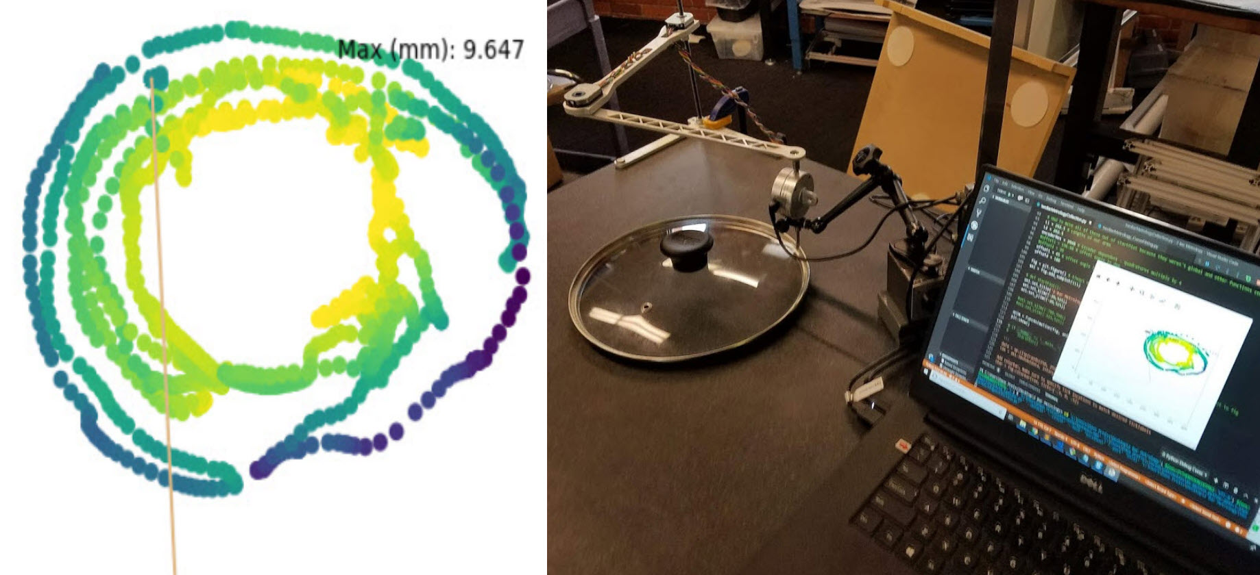
CMM's are typically used to separate these two measurements where XYZ point collection are all automated, and then a plane is fit to the inspected surface. You can effectively achieve the same thing by plotting your points in a spreadsheet, but I wanted to build a tool to automate XYZ point collection for the manual dial indicator + surface plate scenario. I used two AMT102 rotary encoders from another project to create what amounts to a driven SCARA arm that sleeves over a dial indicator (without constraining it in Z), and follows it around a surface plate as an operator takes measurements in Z. Through work I have a script that pulls data via USB from a cheap iGAGING dial indicator, which amounts to measurement of all 3 axes.
Figuring out the trig was relatively straightforward, but there's a caveat which is that as soon as your second arm leaves the 180 deg interior angle of the first (and again after 270) you have to make a few small adjustments to the plotting script. This led me to a day wrangling with plots that looked like the one below. You can see all of the trig in twoBarMetrollogyCollection.py. The plotting script is currently computing the trig for every point, for every frame, because I was lazy about moving from the plotting a complete array to the real time case. I haven't run into any memory limitations yet because most of my plots have been limited to under 2ish minutes.
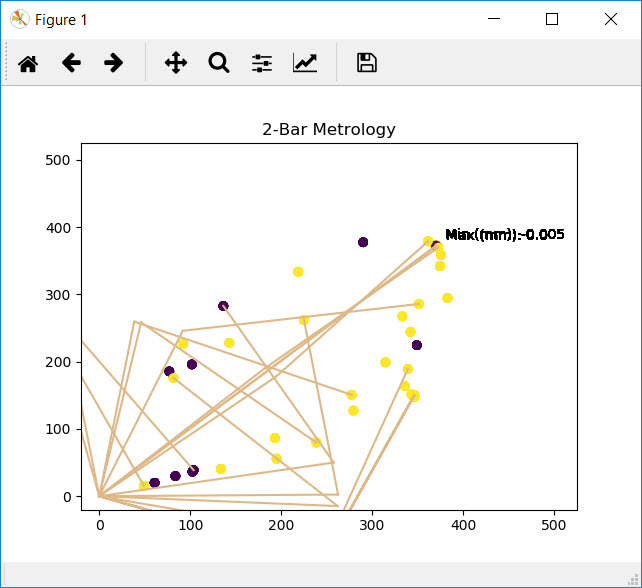
An early scan from when I was still smoothing out some of the trig issues.
This project was my first time using matplotlib's animation features (which is really just iteratively plotting then clearing over a given time interval). It made the move from plotting a single array of points to actually animating it in real time pretty straightforward. There are 3 scripts:
- twoBarMetrologyCSVGenerator - Creates and populates a .csv of Time, Angle1, Angle2, Deflection.
- twoBarMetrologyCollection - Converts .csv to cartesian coordinates and heatmaps.
- twoBarMetrology_CurveFitting - Plots points in 3D and fits a plane to the surface using least squares. Also plots a histogram of point to plane distances and outputs surface flatness, parallelism, and angle.
twoBarMetrologyCollection generates a heatmap of surface height while dynamically updating max and min heights + linkage position (the two lines in gold) in real time.
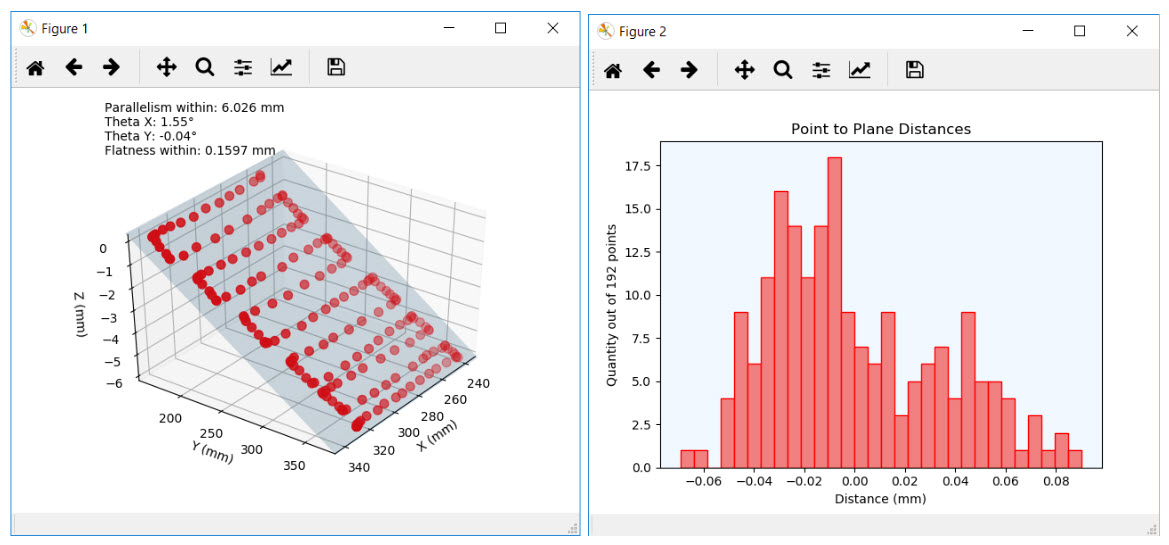
twoBarMetrology_CurveFitting outputs the two plots above.
I scanned a few objects but have yet to use the rig for anything work related. An interesting test I've used to benchmark the jig's performance is to measure the surface of a machined aluminum plate of known flatness, and then put a 6mm gauge block under one end of the same plate, keeping flatness the same, but throwing off parallelism by 6mm. If everything were functioning ideally, the script's flatness estimate should be identical for both scans. Both plots are shown in the video, which nets a flatness deviation of 130 microns (not very impressive accuracy). I am not 100% sure where the error is coming from, but suspect the moment created by the angle might be too much for the dial indicator's bushing (I was scanning upwards and should have been scanning down) and/or the Noga arm I was using also contributed.
One thing this project could really benefit from is a "dead man's switch, where points would cause points to only be logged when the switch was pressed. Currently the rig has to be zeroed every time its started up, and so you have to manually delete noisy points as you can see in the video.
Final ambitions for the project are to switch from the 2 bar linkage to a camera and some openCV to track the top of the dial indicator around the table. Then points could be plotted over an actual still frame of the part being inspected, which would probably be a much more compelling way to send information back to a vendor (particularly if their serial number was visible on the part).
You can find the code for this project here.

The final script is written in python, and uses a lot of openCV and PyTesseract for the OCR. It works by letting a user upload a video of their test setup, grabbing the first frame, and then asking for rectangles to be drawn around individual regions of interest within a sensor's DRO. The script then iterates through every frame of the video looking within each user generated rectangle. Tesseract also provides a confidence score to each guess, so that gets added as well. This method relies on the camera and sensor being relatively static throughout the test.
Most smartphone cameras shoot at 60 fps, so even if you are rejecting 50% of frames you are still getting 30 fps of data, which is excessive for most of the tests that I run. Unfortunately depending on the DRO, you do wind up with a lot of distorted frames where the DRO was flickering between values. 7 segment displays are one of the better options here. Some of the benefits of data acquisition this way are:
- You have video evidence of every test to go back and look for outliers.
- All of your sensors become perfectly synced, so no worrying about stitching data together from different datetime formats or out of sync data.
- You don't need to know how to program to automate data collection from your sensors (ideal for folks in the sciences who don't have hardware data collection chops)
- Ability to incorporate intangible visual data into a test alongside a sensor.
- Motion tracking for the digits of interest to support a moving setup.
- An option to select a pixel or area of pixels and plot their color alongside data from other sensors. (useful for LED's that light up on a PCB when a sensor is triggered)
- An option to select analog dial sensors (such as a test indicator or pressure gauge)

5 Bar Linkage Kinematics
Around the time when Shaper announced the Origin, I became fixated with finding out how they were achieving XY motion in such a tiny package. Where were the linear rails and lead screws?! After looking through more of their documentation I found the explanation, which is a really unintuitive 5 bar linkage with two nested linkages. For Formlabs' 2018 Hackathon I was planning to build one up and try to get it moving. I was lucky enough to convince 4 others to help with the project, and we made some incredible progress over just 3 days. There were two configurations of the stage that I wanted to make - a ~ 1" x 1" travel version for machining, and a comically lanky version for plotting that could be hung from a whiteboard to draw with. With our 5 person team we wound up making both (see picture below and thumbnail).What's especially clever about the Origin's design is that it achieves relatively rigid and accurate (although accuracy is variable) 2 axis motion, without the use of expensive linear motion components such as blocks/rails, belts, or ball screws. Kinematically it's similar to a SCARA, but allows for both motors to be grounded without additional transmission elements, and the added rigidity of having 2 linkages joined at the end effector. Shaper has a particularly compelling case for their implementation. There is no strict requirement to move linearly when you're autocorrecting for a human (we're pretty bad at moving linearly anyways). By limiting their travel to human autocorrect, they can ignore the resolution penalties associated with moving in arcs at 90 deg from inflection. Lastly they nest the bearings for the outer linkages within the inner linkages (see their teardown video or the GIF below of our acrylic version), which allows for a smaller footprint and higher rigidity.
A lasercut version of the more rigid version we ultimately machined in aluminum.
We got Michael Fogelman to join the team which feels a lot like an NBA player showing up at your pickup basketball game. He figured out the forward kinematics and handled all of the non firmware level software (+ some of it) and wrote a complete motion control system in just 3 days.
My final goal for the compact rigid design would be to put one of these stages underneath a vertical tapping machine where you loosely position your hole within a ~1" circle, and the stage positions it underneath the tap with some CV. This would be a neat way to use the mechanism that's still within Shaper's coarse human adjust + fine robot adjust paradigm.
I also want to write a script that shows the linkage's variable resolution by plotting all of the full steps the robot can take and heat mapping them by distance to adjacent points. Unintuitively the robot has highest resolution when both linkages are fully extended. In looking up how to solve the forward kinematics I found a neat paper that lays out all of the potential 5-bar revolute/prismatic joint configurations this robot can take, so it would be fun to try the 2x prismatic case someday.
Parametric XY
Another project I'm including here is some robust master modeled parametric CAD for a Core XY that does a decent job of minimizing footprint. I designed the setup for a work friend who was tracking a laser power meter with a galvo driven laser assembly. Core XY's are a neat means to achieve 2 axis motion. They're particularly useful for low inertia high + speed applications, due to the fact that they isolate several high mass components (particularly stepper motors) from their end effector and subsequent axes.
Form 2's at the time of filming were only capable of driving a single axis at a time.
We got it running off of the wipe and peel motors of a Form2. You can find the model sans build platform and Formlabs related paraphernalia here. It uses some relatively inexpensive standoffs, shoulder screws + bushings, and THK's SRS7-M profile rails (although knockoffs will works as well). I think the layout I've wound up with makes some good compromises between maximizing footprint with respect to travel, mechanical complexity, and rigidity.

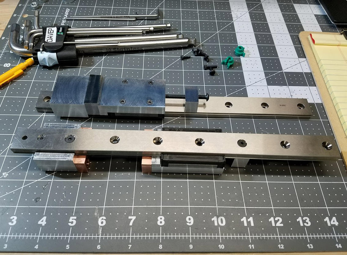
Most machinest's vises use large castings and a lot of mass to ensure rigidity, but the philosophy here is to transmit as much of the clamping load into the base of the machine through the rail as quickly as possible. The moving jaw and nut post index along the mounting holes of the linear rail, so they have a 6" capacity with only 40 mm of stroke. Both the fixed jaw and nut post are mounted from underneath using M4 FHSCS, so the price to pay is that the vises need to be unmounted to adjust capacity. There's a captive nut in a pocket within the moving jaw that attaches to the tightening screw. All of the clamping load goes from the fixed jaw to the nut post, and the linear guide only takes up any moment from off-axis clamping which is relatively low unless you're using parallels.
I made a pair of hard jaws for the vise machined from an old parallel, and another pair of soft jaws from copper for delicate work. All the other components are currently 6061, but someday that will all turn into A2 depending on how useful they are.

For Formlabs' 2019 Hackathon I was initially planning to build up a polygonal scanning mirror and just make a scanner, but convinced two coworkers to join so we decided to tackle something more challenging. A third relatively common application for polygonal scanning mirrors is to generate topographic maps as a part of a plane's LIDAR. They're a good fit for this application because of the high scanning speed and repeatability of the mirror's single rotational DOF. LIDAR is actually just a pretty straightforward time of flight sensor, no different from ultrasonic distance sensing, but with some quirks (non-visible wavelength + pulse at odd frequencies to create a unmistakable return signal).
The device we built scanned at 905 nm (non-visible) in a 60 deg vertical window, and was capable of 360 deg rotation. It sort of has to be said that this is not an ideal scanning method for mapping rooms (unless you have things moving incredibly fast). We started with a very promising LIDAR dev kit from TI
capable of scanning at 4kHz. But couldn't get it working and wound up falling back on a cheap off the shelf sensor called the TF mini, which we spliced our own laser into.
Our initial plan to index edges of the hexagonal mirror using the TOF laser failed because we forgot about the fact that the TOF throw signal was only on intermittently. We got the project to a point where we were getting good distance measurements, but poor scans due to intermittent indexing signal. So our continuing engineering goal for the project is to shine a second low power laser (in the visible spectrum) at 100% duty cycle that is used purely to index each time you pass between facets of the polygon. Overall the project was a lot of fun and I got to use some unusual optical equipment, despite not winding up with a working scanner.
An animation I made while CADing up the scanner showing the laser's 120 deg optical path with varying mirror angle.
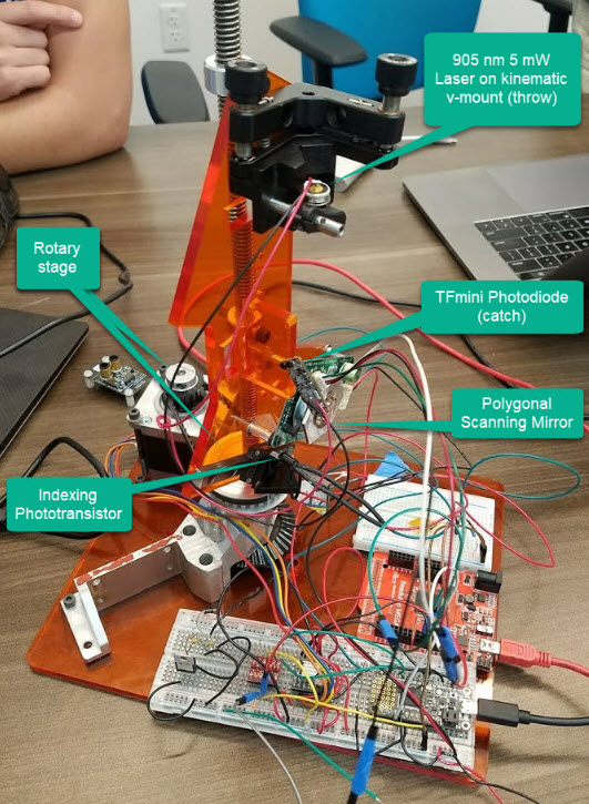
Annotated view of the assembly that hopefully helps in understanding what is going on.
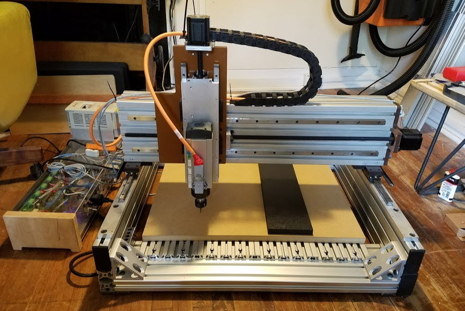
You can see some early video of it cutting here, (ignore the cardboard chip containment). Future plans for this tool are to replace a few remaining phenolic parts with aluminum, a low RPM spindle, rotary axis, and eventually film a machine overview.

A hangboard I machined from eucalyptus
This project is completely open source and you can check out the design on Fusion 360 here. Feel free to get in touch if you are building a tool of your own or have any questions!

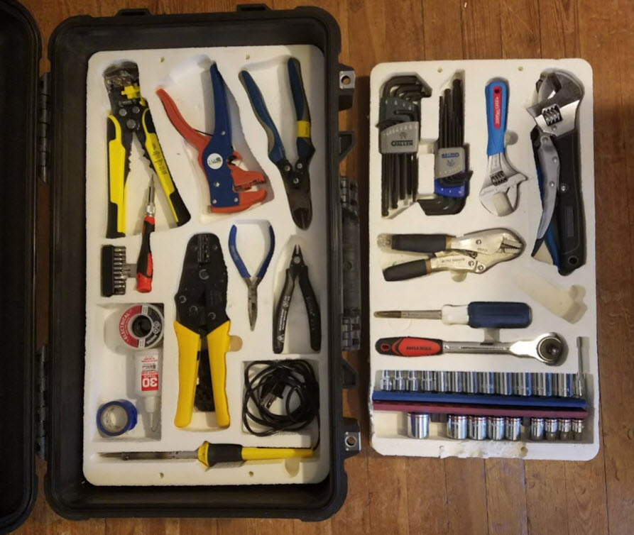
The motor is controlled with a VESC, which is a neat open-source speed controller originally designed for DIY electric skateboards. VESC's can push up to 50A continuous at 60V which is significantly more power than I need (I am pulling about 26A at 30 mph which is about as fast as I feel comfortable on a bike). The VESC also has a 5V BEC and is capable of reading resistive or hall effect throttles, which would otherwise have to be overcome with an arduino or servo-tester circuit. VESCs are also capable of some neat functions including regenerative braking and FOC control which I am looking forward to experimenting more with. I built the battery pack into a pelican case and wired in some schottky diodes for backcurrent protection, as well as a solid state relay (the glowing blue external power button). The battery pack is actually completely waterproof at the expense of poor cooling.
The motor is mounted between the seat stays and seat tube and is geared down to the rear wheel with a 2-stage HTD 5mm timing belt reduction of about 10.6:1. I started with a large plywood rear pulley located concentrically with the hub of the rear wheel and zip tied to the spokes of the wheel. I foolishly thought it would be fun to design a freewheel and build it from scratch which you can see a picture of below. I designed and machined/printed all of the parts in the freewheel aside from the bearing. The pawls are machined from 5160 spring steel, but the ratchet I never got around to waterjetting it in something that wasn't aluminum (note the aluminum shavings in the mounted picture below). The freewheel worked for about 2 weeks of daily commuting and then jammed and failed catastrophically when the acrylic pawl retention cover cracked. Since then I haven't had the heart to return to the project, but will eventually replace the custom freewheel with an OTS one mounted to the hub and a waterjet sprocket.
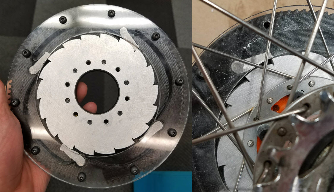
A custom freewheel I made for motor to rear hub transmission.
Somehow this is the only video I have of the bike actually running - pre freewheel and final battery pack.

Each part included 5 tool changes and moved through 3 setups to achieve a total machining time of under 2 hours, while minimizing post-production through slot milling for the frames, machining for all hinge mounting hardware, and using extremely tight finishing stepovers. All workholding, part location, and tool changes were integrated directly into the machining process through a series of prompt-driven macros, allowing the parts to be manufactured by any shop employee.
3-Axis slot milling toolpath used for lense grooves.
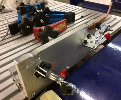
Locating jig for final hinge-hardware machining. Toggle clamps were used to locate and hold-down temple arms in their negatives.
Automatic Tool Changer Redesign
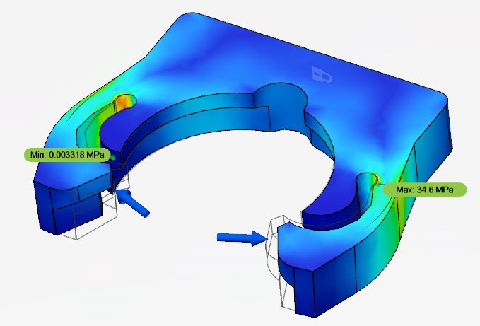
An ATC, or Automatic Tool Change System, is used by a CNC tool to eliminate the manual steps in a tool change, allowing for rapid production times. I designed and sourced a pneumatics system in collaboration with our vendors for the tool release, positive pressure, and cylinder with precission regulator to balance the weight of the tool’s z-axis. This included an in-house manufactured tool clip (The FEA for this part is shown in the thumbnail) for accepting tool holders when not in use, and changes to the toolbar's design that drastically reduced cost by eliinating a pneumatically actuated dust skirt previously necessary for the ATC.

Dust Shoe Redesign
I led the redesign and manufacturing worflow for a series of dust shoes compatable with each of ShopBot’s 5 cutting tools. The redesign was backwards compatable and utilized shared non-fabricated parts for all iterations of the dust shoe. The redesign drastically reduced cost by eliminating powdercoated sheet metal parts, maximizing sheet yield, and adding a magnetically removable shroud for ease of use.
5-Axis Redesign
I led the testing and handled redesign specific changes for ShopBot’s 5-Axis tool. I built the first prototype using the new beam design and made as-built changes to the tool, which were ultimately incorporated into the product's engineering master. This included a new Z-axis cable carrier, proximity switch mounting and their associated macros, cable lengths and management.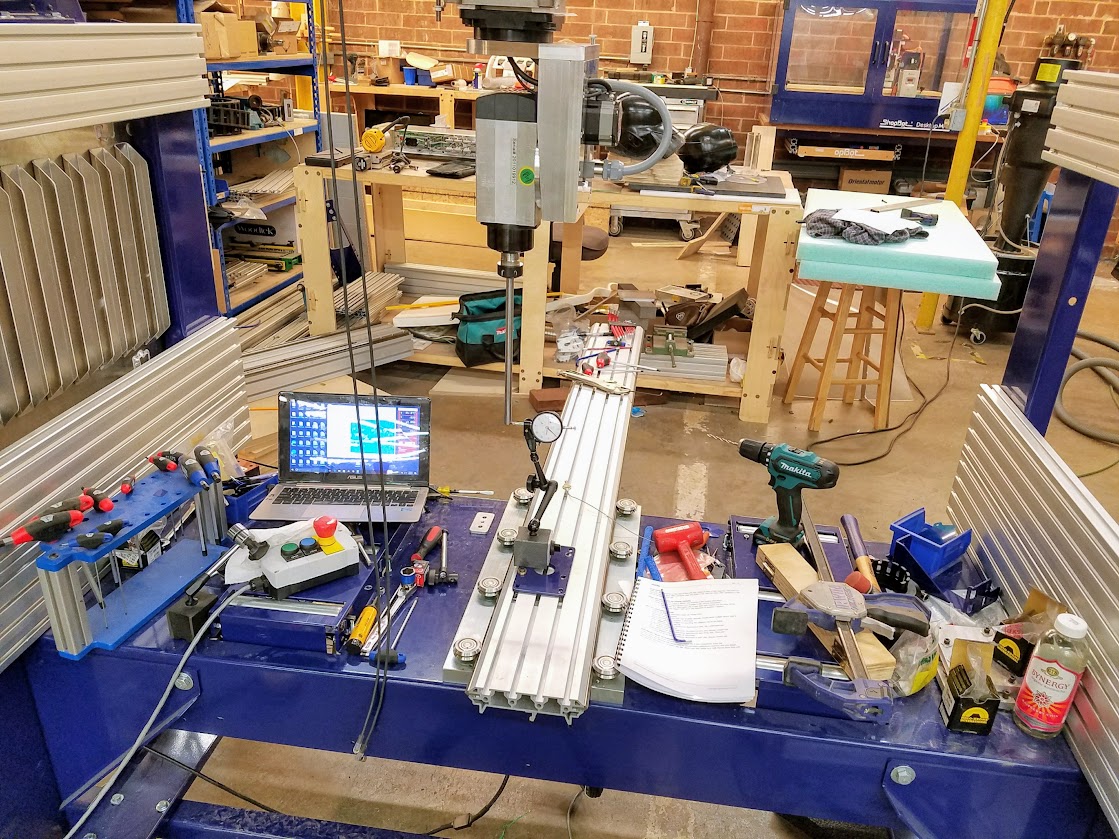
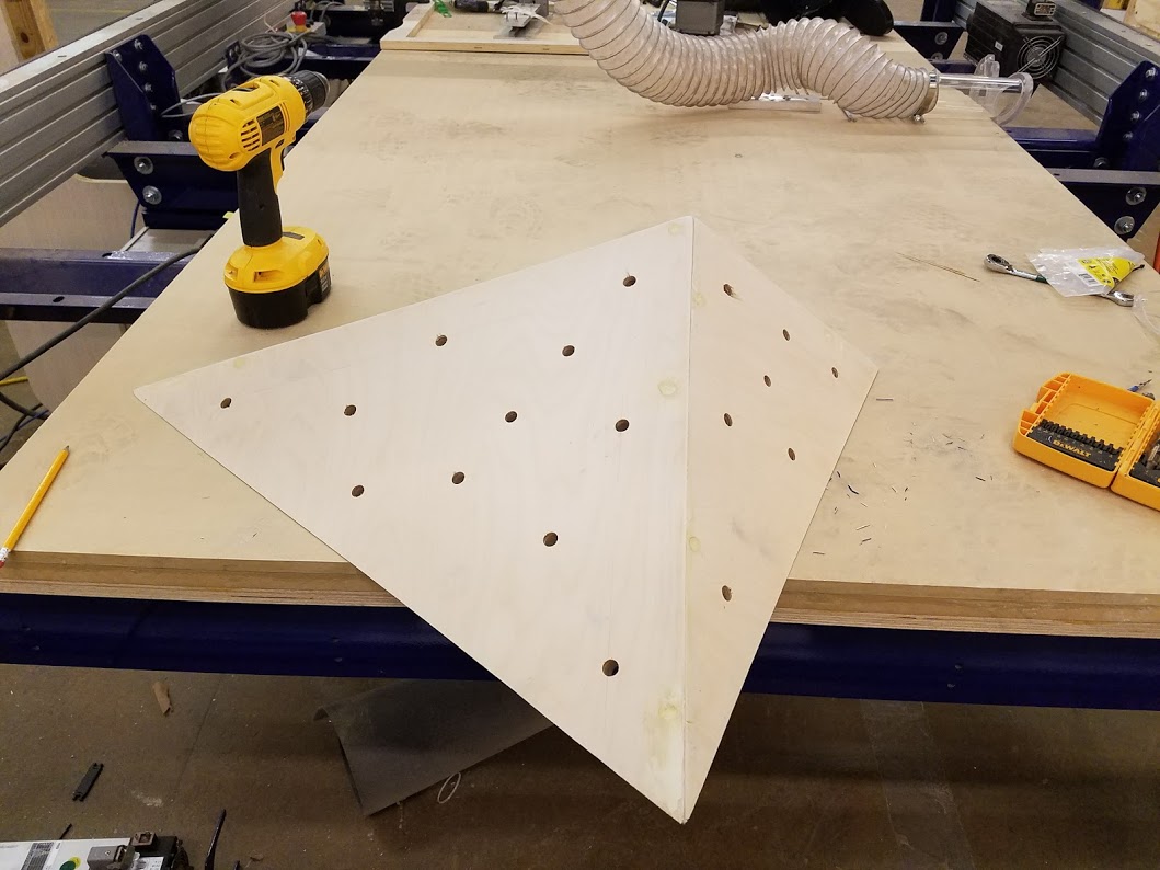
Climbing volumes are primarily sold pre-assembled, which typically includes a finish coat of paint or epoxy, mixed with an aggregate material to provide gripping texture. Holes for screw in t-nuts are also added, and are used for bolting additional holds to the volume. Depending on volume geometry, final volume (length^3 in this case) can increase by an order of magnitude in comparison to flat packed volume which effects shipping costs.
Animation showing parameter adjustments made to a 4-sided polyhedron. Not shown is the flat-pattern geometry and toolpaths adjusting in real-time.
I have modeled several of the most common climbing volumes parametrically, such that custom volumes of any desired dimension can be generated. The volumes are then copied and mated flat to a 4x8’ sheet of pywood. Parameters can be updated resulting in the 3D model of the volume to update, but also the flat pattern in real time, allowing for efficient nesting. The most novel aspect of this project is that the miters are cut through a 3D offset carving operation by a CNC tool, allowing for unrestricted convex miter angles to be cut. Edge quality is directly proportional to stepover, but a stepover of 0.03” has been found to work well for a 45 deg miter, which can be cut rapidly and in a single operation. With adequate vacuum hold-down, tabs were not found to be necesary, and parts can come directly off of the tool ready for glue-up and assembly. The greatest benefit of this process comes in maximizing nesting efficieny, resulting in more efficient material use.In the summer of 2017 I cut a pair of volumes and after assembling and finishing, donated them to my local gym. Since then I have sold several sets to local gyms as well as friends with an at-home bouldering gym.
Models for this project can be found here, and if you are interested in cutting some volumes of your own/parametric modeling in Fusion 360 in general, or app development with the API feel free to get in touch via email!
Future goals for this project are to develop a complete Fusion-360 add-in, and eventually a web interface where customers can generate custom volumes of their own in real time.
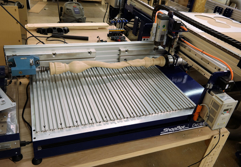
Three weeks before the conference, initial plans to ship a gantry-style indexer were canceled due to size constraints of the building’s service elevator. I began working on adapting the Indexer to the Desktop Max and had a working prototype
in two weeks time. The prototype was used as a part of a 3 day workshop in collaboration with a team from University of Minnesota’s DesignFab entitled “Exploring the Fourth Dimension.”
After positive
feedback from the event and several several customer inquiries, I adapted the prototype to a production ready design, which is sold as a standard product for ShopBot’s Desktop line of CNC tools. The Desktop Max 6” Indexer is also used
frequently by ShopBot to demonstrate rotary CNC work both in house and on the road.
You can find more information at the Desktop Max 6” Indexer Product Page.

After sourcing a compatible tangential knife, I designed, built, and tested a prototype of this product for a customer requiring a custom dual-z machine, capable of both cutting and machining material up to 4” thick. The final tool was capable of switching between tangential knife and machining operations mid-toolpath, and the tool handling for the knife was integrated directly into the ShopBot control system.
This project involved a variety of custom electrical and mechanical hardware. I also worked closely with software engineering to develop a secondary post-processor to add tangential 4th axis motion to native ShopBot code when the tangential knife was called.
The final design lowered cost and build time by integrating PEM hardware in several places and shifting complexity in parts from powder coated steel sheet to an uncoated aluminum. The redesign also oriented the tool’s drivers vertically to allow for more efficient natural convection across the rear of the tray which doubles as a heatsink.
The redesign allowed for an additional row of aluminum decking to be installed at the rear of the tool, such that an Automatic tool changing system, Fixed Z-Zero Plate or Indexer/other accessory could be mounted permanently to the tool without sacrificing work area, or to utilize an additional 2” of machining area. The changes have since been incorporated into ShopBot’s 24” x 18” Desktop redesign.
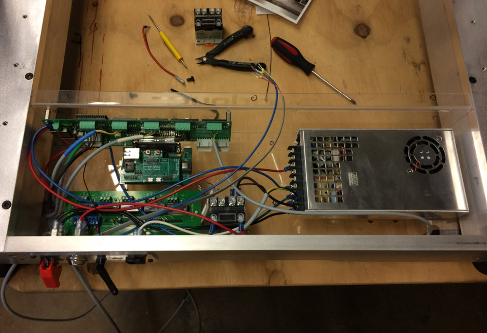
I used a prototype of the redesigned tray in a custom modular CNC controller that I built for my personal machine, but the design can be used pretty generally for building CNC enclosures using Gecko G250X drivers and ShopBot’s Desktop control board.

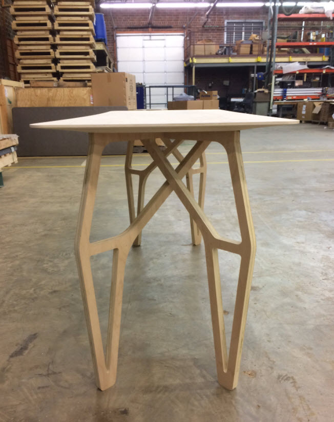
The desk shown above was designed parametrically, meaning that its model was constrained by a series of variables which allow for rapid design changes. The animation above shows parameter changes including desk width, depth, and leg height, which could be used to change the desk's function from a work desk to a console table. The desk can be disassembled and flat packed into 5 pieces, and assembles using mortice and tenon joinery (requiring no fasteners or adhesives) in about 2 minutes.
The files for this project are open source and fully parametric, meaning that variables such as material thickness, height and width can all be changed dynamically, without having to directly edit the 3D model or update the machining operation. In some cases the layout of the final flat pattern must adjusted. Feel free to get in touch if you are interested in working with these models or have any questions!Models including all necessary CAD and CAM for this project can be found here.
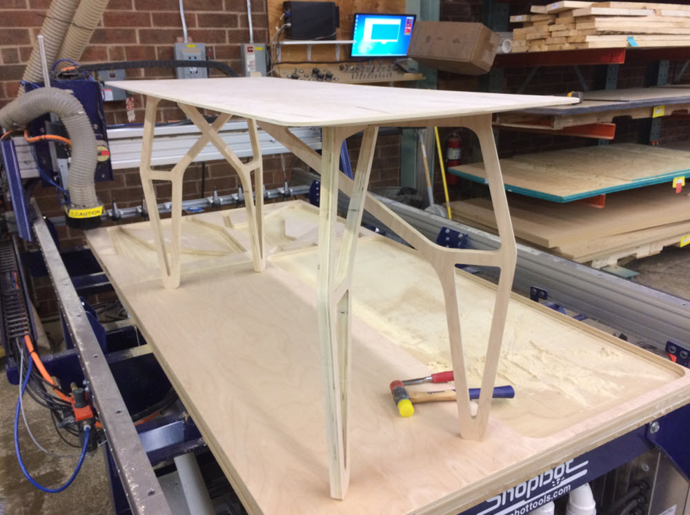
The desk configured as a work table, shown assembled immediately after manufacturing using only a chisel for tab removal and mallet for assembly.

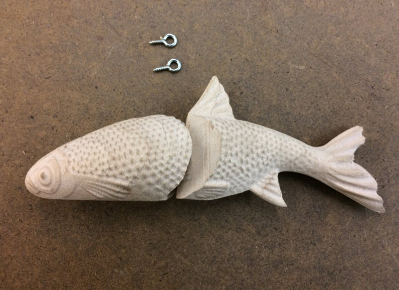
As part of the product's testing procedure, I machined several parts in both 4 and 5 axis. The swimbait shown above was machined in two operations with the accessory in the 4 axis configuration, and is a good example of the way the accessory can be used to expand a 3-axis tool at minimal cost.
For more information on this project check out the Setup and Use Guide.Or a case study on machining in 5-Axes using the accessory.
And finally here is an open source guide to building one, as well as the accompanying .STP files.
Other work I have contributed to the Handibot includes the design of the Handibot Hood, which was sold as an accessory before being incorporated into the tool in version 2, as well as a redesign for version 2of the Y and Z axis to maximize travel and reduce overall height.
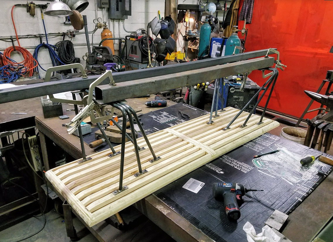
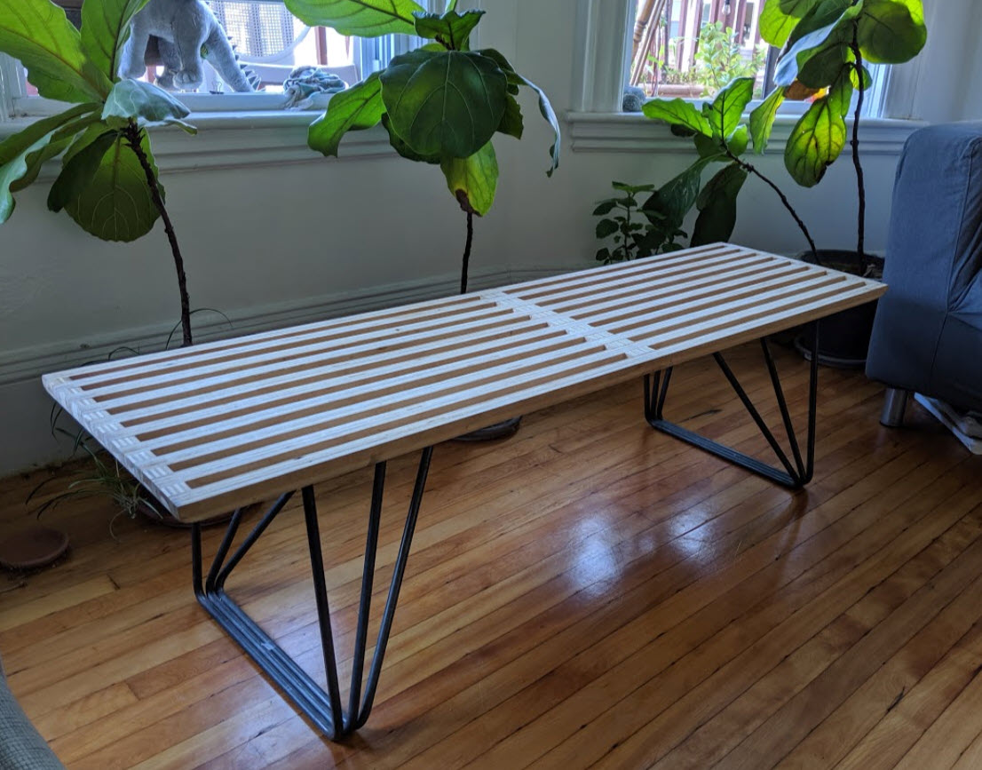
After building the bench top, I added the loft shown below, and fabricated a pair of steel legs inspired by mid-century style hairpin legs. Design constraints for the legs were that they be strong enough to support two people, and that their fastening method be hidden when looking at the bench from above. The final design achieves this by bracketing to each slat individually, which also helps in distrubuting load accross the depth of the bench. I built the legs with help from my uncle at ARP Design. In the future I hope to publish a more detailed walkthrough for this build, but have made the models available below!
To soften the bench's hard rectangular geometry, a variable lofted fillet was milled from the underside of the bench top using a ball-nose bit after the initial glue-up.
The files for this project are open source and fully parametric, meaning that variables such as material thickness, height and width can all be changed dynamically, without having to directly edit the 3D model or update the machining operation. In some cases the layout of the final flat pattern must adjusted. Feel free to get in touch if you are interested in working with these models or have any questions!Models including all necessary CAD and CAM for this project can be found here.

Design constraints for the final product were that it be backwards compatible with all existing ShopBots, repeatable to within +/- 0.001” of an inch, and be able to used to zero directly to the surface of material to be machined, as well as mounted in a fixed location to zero to table surface.
More information on the plate’s final design can be found in a blog post here
The plate is currently sold as an accessory and has been incorporated directly into ShopBot’s ATC system, as well as the HandiBot.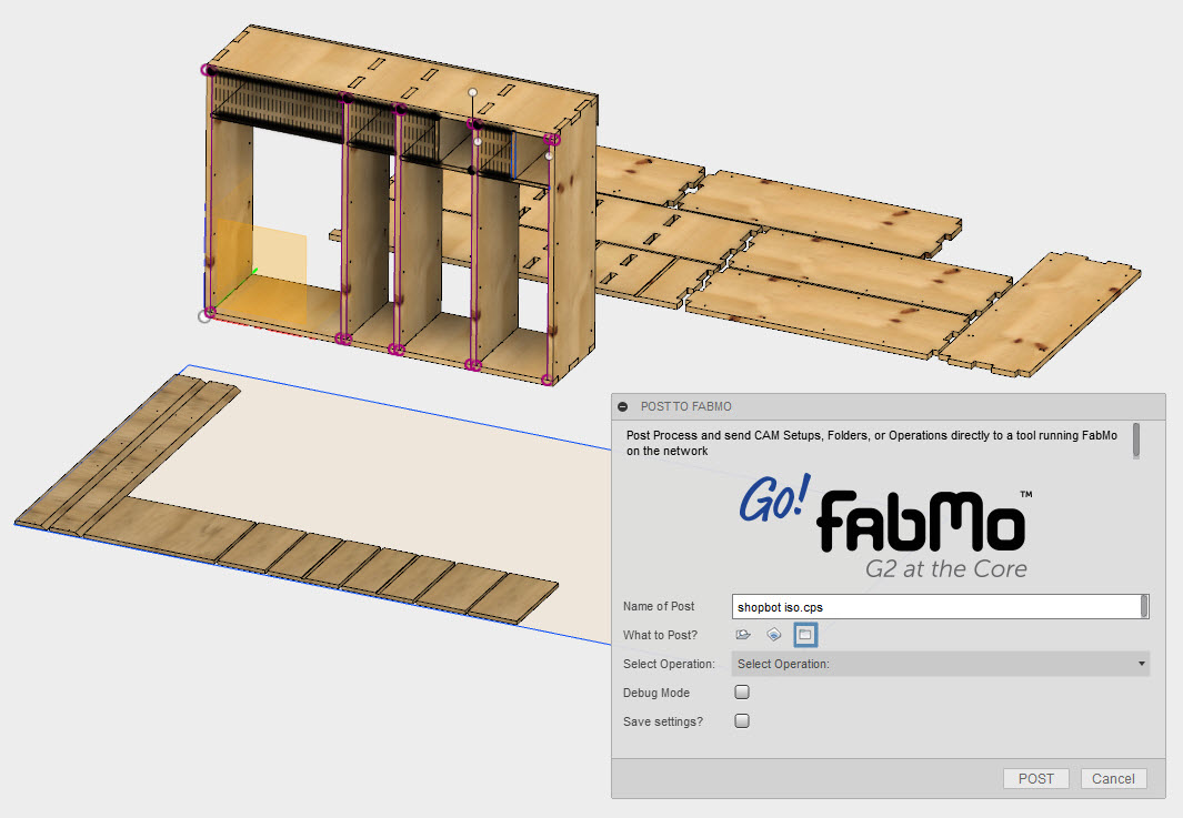
The screenshot above shows the add-in's GUI which allows for the selection of custom post processors, posting of Folders, Setups, and individual Operations. The current prototype version of the add-in will search the network for a single tool network connected tool (doesn't currently work for AP mode), automatically post process the selected CAM files and launch a browser with the found tool. Here's a guide on installing custom Fusion 360 add-ins if you're interested in trying it out.

In visual basic, I programmed a tool handler that created a database of tools for the quick change spindle and applied offsets, including options for dual-z spindles, as well as fixed z-zero plates. The handler was fully integrated into ShopBot’s control system and is currently in use on two custom machines.